Why VFD Wiring Is Different From a Standard Motor Starter
A standard across-the-line motor starter is simple to wire for remote control: close a dry contact between the start and common terminals, and the contactor energizes, connecting the motor directly to line voltage. The FarmHQ relay provides that dry contact. Installation is typically 20-30 minutes.
A variable frequency drive (VFD) doesn't work that way. A VFD includes its own microcontroller that manages the motor's ramp-up profile, monitors current and temperature, and handles fault conditions internally. The VFD's run-enable input is a low-voltage control input — typically 24VDC or a dry contact closure into the VFD's internal 24VDC reference — that tells the VFD to begin running the motor output. Bypassing the VFD's control logic to apply line voltage directly to the motor terminals would damage the drive and void the warranty.
There's also a safety consideration: VFDs are designed with safe-stop and safe-torque-off functions that a remote relay must not override. The FarmHQ installation must interface with the VFD at the control input level, not at the power level, to maintain the VFD's safety behavior.
Approach 1: Direct Control Terminal Wiring
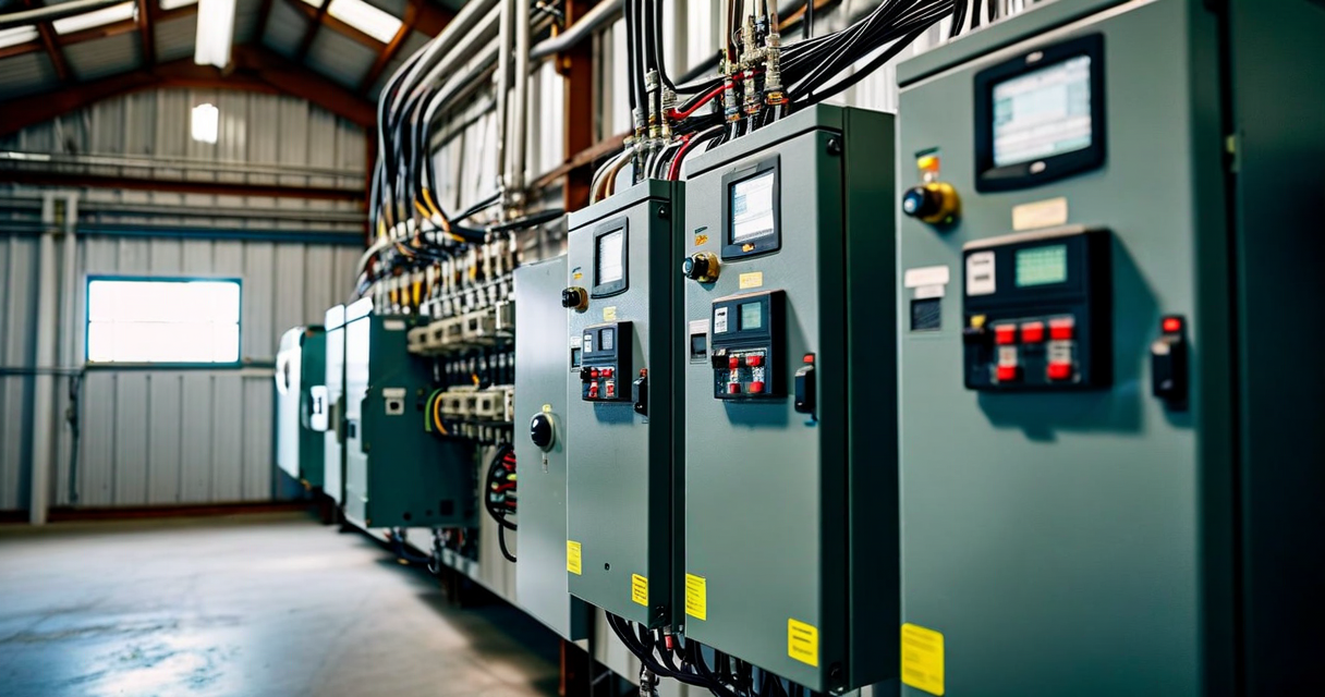
Most agricultural VFDs — including the Allen-Bradley PowerFlex 40, the Yaskawa V1000, and the Danfoss FC-102 series commonly found in irrigation pump applications — have a standard 2-terminal run-enable input on the control terminal strip. This is a dry contact input: close the contact, and the VFD starts running the motor per its programmed speed reference and ramp profile. Open the contact, and the VFD stops.
FarmHQ's relay connects directly to those two terminals. The wiring is simple: run two-conductor 18 AWG wire from FarmHQ's relay output terminals (NO and COM) to the VFD's Run and Common control terminals. On most drives, these are labeled DI1 (Digital Input 1) and DCM (Digital Common) in the control terminal strip documentation. The specific terminal designations differ by drive manufacturer — always check your VFD's terminal strip diagram before wiring.
Important: confirm that the VFD is configured for 2-wire control (run/stop via maintained contact, not a momentary start/stop logic). Most drives ship in 2-wire mode by default for irrigation applications, but drives that were previously used in other applications may be configured for 3-wire mode (separate start and stop contacts). A drive in 3-wire mode will not respond correctly to a maintained run contact from FarmHQ's relay. Change the drive's control mode parameter to 2-wire before testing.
After wiring, test the installation manually before relying on remote control: with the VFD powered and FarmHQ's relay in the open (off) state, confirm the motor is stopped. Then send a run command from the FarmHQ app and confirm the relay closes, the VFD ramps up to its set speed, and the motor runs. Send a stop command and confirm the VFD ramps down and stops. Check that the VFD's local fault history shows no new fault events from the transition.
Approach 2: Using a Bypass Switch for Manual-Override Capability
Some pump operators need a manual override capability — the ability to run the pump from the panel if the FarmHQ module loses power or cellular connectivity. Without a bypass, a FarmHQ module that's offline leaves the VFD with no run signal, and the pump can't start locally.
The bypass solution is a 3-position selector switch (Hand/Off/Auto) installed in the control terminal circuit. In the Auto position, the circuit routes through FarmHQ's relay — remote control is active. In the Hand position, the circuit bypasses FarmHQ's relay and closes the run contact directly — the pump runs continuously regardless of FarmHQ state. In the Off position, the circuit is open and the pump cannot run from either source.
Wiring the selector switch: the VFD's run terminal receives its signal from one pole of the selector switch. In the Auto position, that pole connects through FarmHQ's relay (relay NO terminal to relay COM terminal, then to the VFD common). In the Hand position, that pole connects directly to the VFD common without going through the relay. A 3-position cam switch with 2 NO contacts on the same shaft provides this logic cleanly. The same cam switch position wiring is described in detail in the FarmHQ VFD installation guide (downloadable from the product documentation section of farmhq.org).
Speed Reference Wiring for Variable Speed Operation
If your VFD is programmed to run at a fixed speed (a common configuration for irrigation pumps where constant pressure is desired), no additional wiring is needed beyond the run-enable contact. The VFD runs at its programmed speed when the run contact closes.
If you want to vary pump speed remotely — for example, to reduce speed during early morning hours to conserve energy, or to modulate output based on a downstream pressure setpoint — FarmHQ's analog output can drive the VFD's speed reference input. FarmHQ's analog output provides a 4-20 mA signal that maps to 0-100% of the VFD's maximum programmed frequency. The VFD's AI1 (Analog Input 1) terminal accepts this signal with a 250-ohm impedance termination resistor.
Variable speed control through FarmHQ is a more advanced configuration that requires careful tuning of the VFD's speed ramp parameters and the FarmHQ schedule's speed reference settings. It's most commonly used in pressurized drip system applications where maintaining a specific header pressure matters more than running at constant speed. Contact [email protected] for help with variable speed configuration for your specific drive model.
Fault Monitoring: Reading the VFD Fault Output
Most VFDs include a digital fault output relay — a dry contact that opens when the drive is in a fault state (overtemperature, overcurrent, phase loss, communication fault). This output can connect to FarmHQ's digital input channel, providing a fault signal that FarmHQ can report via SMS alert.
Wiring the fault output: run two-conductor wire from the VFD's relay fault output terminals (typically labeled RO1 and ROC on Allen-Bradley drives, or MA and MB on Yaskawa) to FarmHQ's digital input terminals. Configure the FarmHQ digital input as "VFD Fault" with alert priority set to high — this is the signal you want delivered immediately when the drive trips.
With the fault output wired, FarmHQ's dashboard shows VFD fault state as a separate indicator alongside the pump running status. A VFD trip while the pump command is active appears in the alert log with the exact timestamp, allowing you to correlate the fault event with pump current and pressure readings from that same period. That diagnostic data often points to the fault cause without requiring a drive technician to make a site visit.
Common Wiring Mistakes and How to Avoid Them
The most common wiring error in VFD installations is connecting FarmHQ's relay to the wrong terminal — the relay output is 120VAC or 240VAC rated, but most VFD control inputs are 24VDC logic. Never apply line voltage to a VFD control input terminal. FarmHQ's relay is a dry contact (no internal voltage source), so voltage is not an issue from FarmHQ's side — but if the relay is being used in a circuit that already has a voltage source, verify that source is 24VDC and not line voltage before connecting to the VFD control strip.
The second most common issue is shielded cable requirements. VFD control wiring runs near high-frequency PWM switching noise from the drive's output section. Running unshielded control wire parallel to VFD power wiring for more than 6 inches can cause control signal interference. Use shielded 18 AWG instrumentation cable for any runs longer than 18 inches within the panel, and ground the shield at the FarmHQ end only (not at both ends, which creates a ground loop).
If you're uncertain about the wiring approach for your specific drive model, email [email protected] with your drive model number and we'll send the specific terminal strip diagram and parameter settings for your drive. Most major agricultural drive models — Allen-Bradley, Yaskawa, Danfoss, ABB, Schneider Altivar — are in the FarmHQ wiring reference library.